For problems of this kind, it is tested whether it is a problem of PC unit, monitor or cables.
We make sure the jacks are securely fastened everywhere (we can also measure electrical signals and voltages).
If we do not have a measuring device - however the device does not have to be complicated, I have one taken from the market with few bucks over 10 years ago and it is something like the one from the the below image:

- remove the cable from the monitor input (VGA / DVI, maybe newer models have other options like USB or HDMI);
- we mount it on another monitor or laptop or TV display or maybe even the tablet that has such an input - this way we check the PC unit and the connecting cables, eliminating or leaving these (unknown) ones in the equation - in my case, I quickly put it on the TV which displayed everything OK.
- Now, LCD monitors theoretically require a bit more technology in a smaller, more compact space. Obviously, the modules are also more compact, theoretically having more active elements and more integrated circuits than - say - CRT monitors.
- My model is a Philips 200CW 20.1-inch / widescreen TFT, and disassembly starts with the front frame that pulls outwards (for the user, say), using a card or plastic tool to separate it from the rest of the monitor (pay attention to right-down buttons, where we have a connector cable for transmitting control signals):
So my problem was from the monitor (of course, and here I checked the connectors, the power supply - everything OK).

LCD widescreen monitor 200CW8FB/00
Philips 200CW Wide - Photo source: philips.co.nz
Obviously there are a number of screws that we carefully put on the work table (they are quite small). Even more screws will be found in the back, because, after undoing the monitor's leg, we will also undo the back cover and the metal protection from the inverter and controller (electronic area).
The structure of the components is somewhat similar to the one in the diagram below and can be applied for many other monitors:
LCD monitor component diagram.
Photo source: scielo.br
If we have screws of different sizes (and we had here), it is good that before each disassembly we take some pictures to make sure that the parts and screws do not remain in addition to the assembly. :-)
Before getting into complicated measurements, after - possibly - we also find a diagram on the internet, the first step is to perform a visual verification at the component level - mechanical level checking: if we have visible or damaged parts or circuits or visible sockets / cables affected.
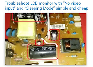
In my case, I identified a few electrolytic capacitors with the swollen top - that is, the dielectric failed (it is interrupted or in short-circuit when measuring the capacitor's resistance with the ohmmeter, for instance) and needs replacement.
As a rule of thumb, a more thorough check is made at the level of voltages and electrical signals, especially at elements such as chips or integrated circuits. In condensers it is a common thing, especially after 10 years of operation.
Defective electrolytic capacitor, upper part swollen:
electrolitic capacitor faulty defective ready to explode the dielectric
Some capacitors look suspicious and are quickly identifiable:
Capacitors / condensators from the PCB
For the safety of the operation, it is advisable to replace the entire group of capacitors that looks or not more or less suspect, even if it was at the beginning - as a maintenance, if you want.
Group of defective capacitors or with potential for failure soon:
The capacitors that need to be checked and changed
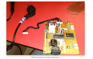
With an usual soldering iron (which can be found in specialized or general stores or hypermarkets or even in markets) of 50 - 60 - 80 W at a starting cost of approx. 10-12 USD, we proceeded to replace all suspicious capacitors.

PCB and maybe the simplest soldering iron
Price?
I think that at 0.1...0.5 $/ piece, with about few bucks I had the whole group of new capacitors.
Another aspect that I must emphasize is that I respected their capacities, instead of voltage I increased (eg instead of 4.7 microfarads / 25 V I took 35 V, even if there is a stabilization, there is an area to absorb any voltage spikes).
As an observation I also add that there is the possibility that after replacing the capacitors the monitor will work for a short period and then again failures will occur (this or another) - so, if initially we used new parts, suitable as values and quality, probably there are more advanced problems and it is necessary to consult a scheme for advanced measurements or a specialist.
240Pcs 24 Value 10V 16V 25V 50V Metal Electrolytic Capacitors Assorted Assortment Kit Set,
Lable Capacitor Range 0.1UF - 1000UF
I am thinking now that if the monitor is old enough and we cannot manage to solve the problem so easy, it is worth thinking of purchasing a new one.
Good luck with that or have fun! ;-)


